
HOW TO USE THE ENGINEBOX
The EngineBox is a device to measure data from several analog sensors and translate the information to messages on the NMEA 2000® bus. It supports resistive sensors (0-400 Ohm), voltage signals (0-5 V), frequency signals (0-4 kHz) and our capacitive level sensors (4-20 mA).
The EngineBox also contains a SAE J1939 to NMEA gateway function.
For setting up a system with the EngineBox the "Veratron Configuration Tool" software and the NMEA to USB converter "Veratron Diagnostic Tool" are required.
If you do not have this tool, ask your local Veratron dealer to program the EngineBox for you.
ENGINEBOX INSTALLATION
12/24V - GND - IGNITION
For the EngineBox to power up, three connections must be made.
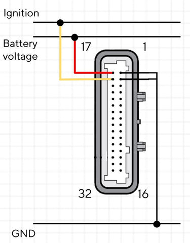
Connect the device to ground and to your voltage source. (12V or 24V)
Connect the yellow wire to the ignition signal. This signal can be 12 or 24 volts too.
When the connections are done correct, the little LED next to the plug is blinking to indicate, the EngineBox is running.
SENSOR CONNECTIONS
The following schematic shows how to connect a resistive sensor to the EngineBox.
Look up the installation instructions, to find out which pins are resistive type inputs. There you can also see to which colored wire on the included harness this pin corresponds to.

To get the most accurate measurement results, it is recommended to use two pole sensors (insulated return). Try to connect the sensors ground as close to the EngineBox's ground connection as possible.
The same procedure applies for the voltage and frequency sensors.
More information about the connection of the capacitive sensors can be found in this separate paper. <add link>
NMEA 2000 NETWORK
The minimum NMEA 2000 network required to use the EngineBox looks like this:

Make sure your NMEA backbone has two terminating resistors on the ends and that the network is powered by a 12V source.
Connect the EngineBox with the included DeviceNet Micro-C M12 connector to the backbone.
To see the measurement values there must be a displaying device on the network (for example an OceanLink 4.3'' TFT Display).
CONFIGURE THE ENGINEBOX
To configure the EngineBox, the Veratron Configuration Tool is required. The software can be downloaded here: Configuration Tool download
Open the EngineBox Input Configurator in the Veratron Configuration Tool by clicking on the button "EngineBox".
Select the according EngineBox in the drop-down list.

To configure one pin as an input for a certain sensor, do the following steps:
- select the sensor type from the drop-down list (The colored rectangle next to the pin number represents the color of this input pin on the wire harness.)
- define the instance for this measurement (note, that counting starts from zero)
- define the sensor curve. For Veratron sensors you can select one of the predefined standard curves. If you have another sensor, write 5 points out of the according sensor curve into the table.
- click on "SET" to load the defined configurations to the EngineBox or push "SET ALL" to load the configurations of all pins at once.

Repeat these steps for all your sensors and check whether you can see the expected values on your NMEA 2000 display.